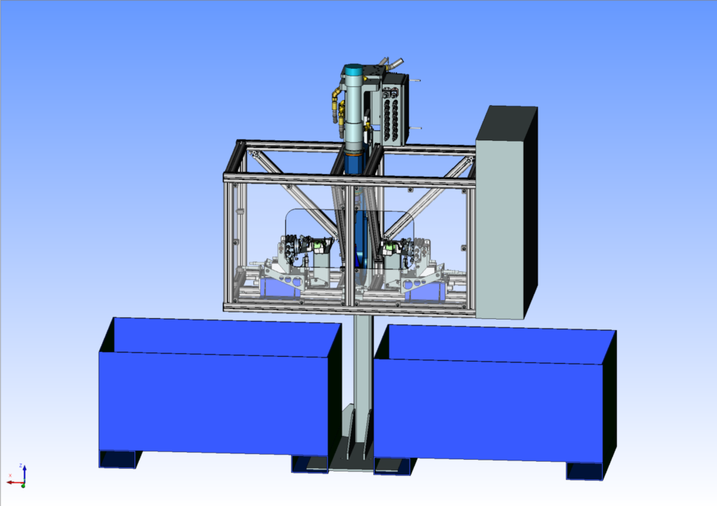
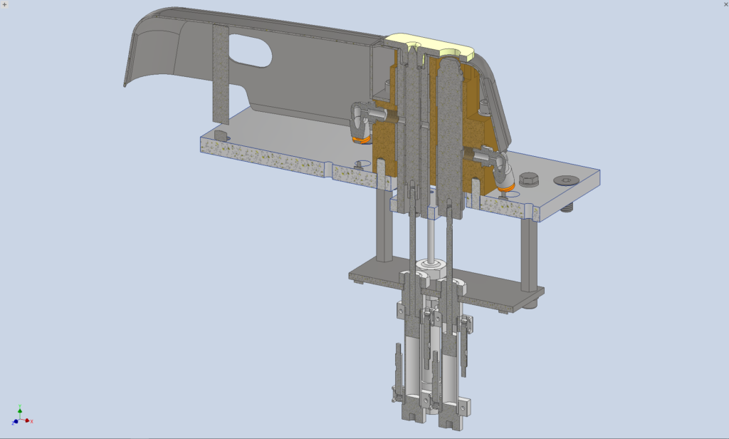
Preparation of preliminary design (3D model) and drawings for client verification
Technical Design
Design documentation
The biggest challenge
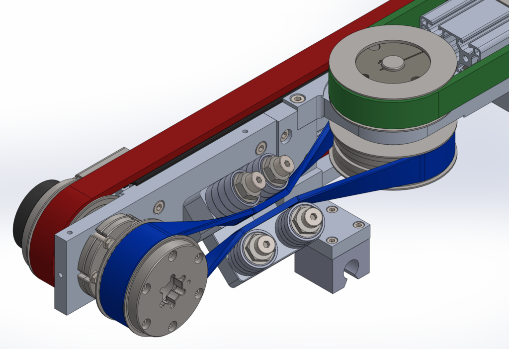
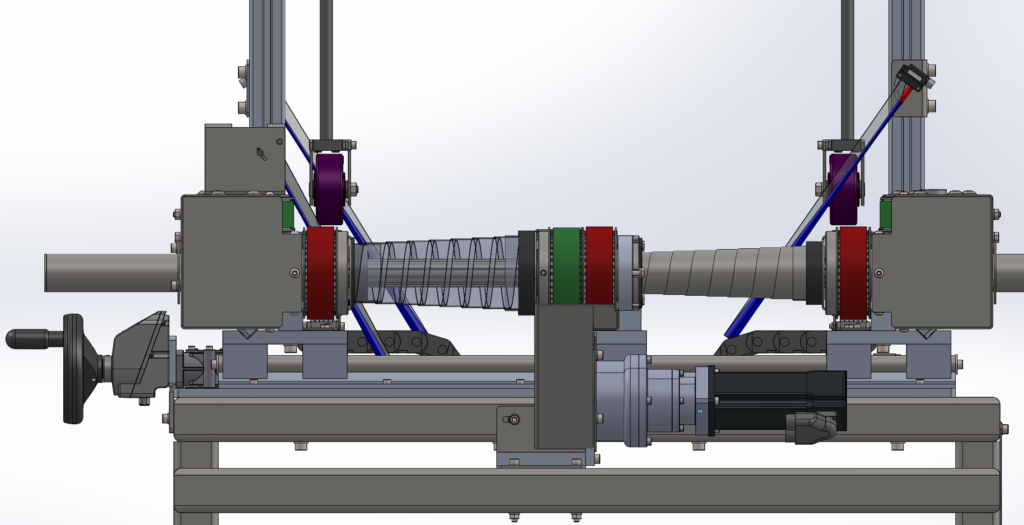
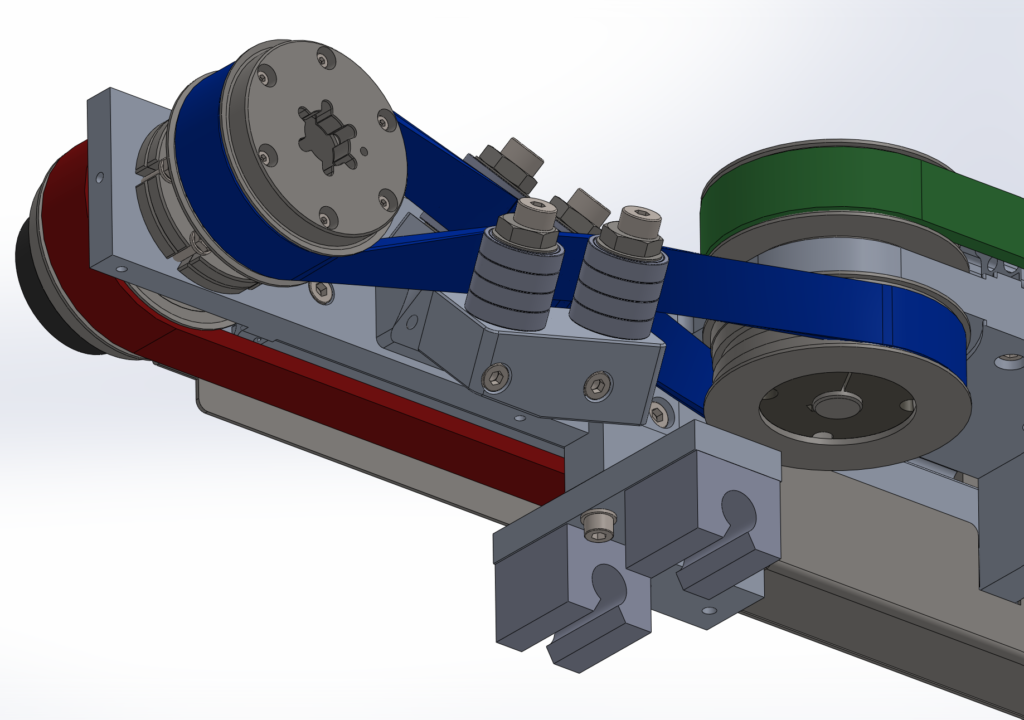
Synchronization of the lower and side belts.
Solution
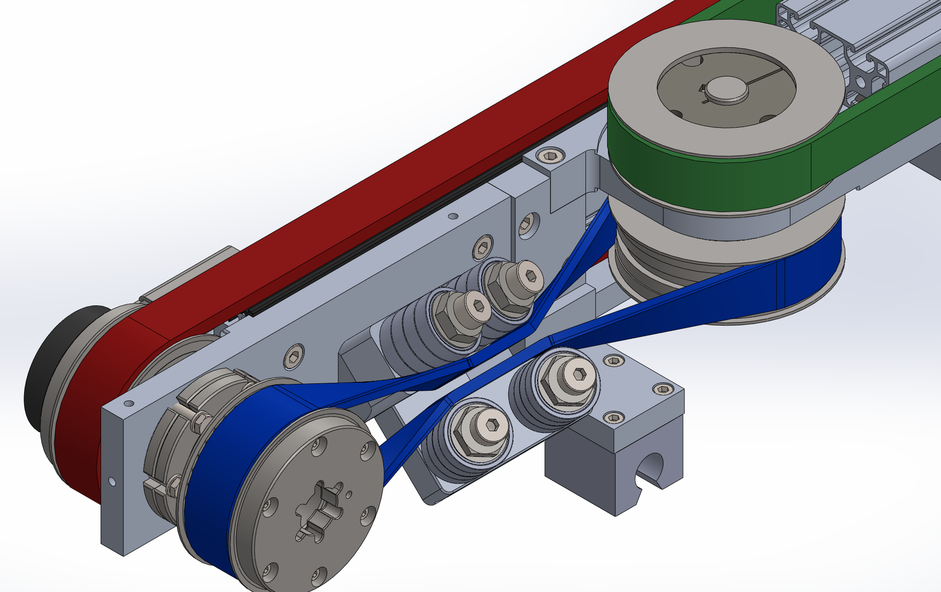
A twisted toothed belt transmission allows for the connection of two axes that are not in the same plane. The key is finding the correct positioning of the belt deflection rollers.
Project description:
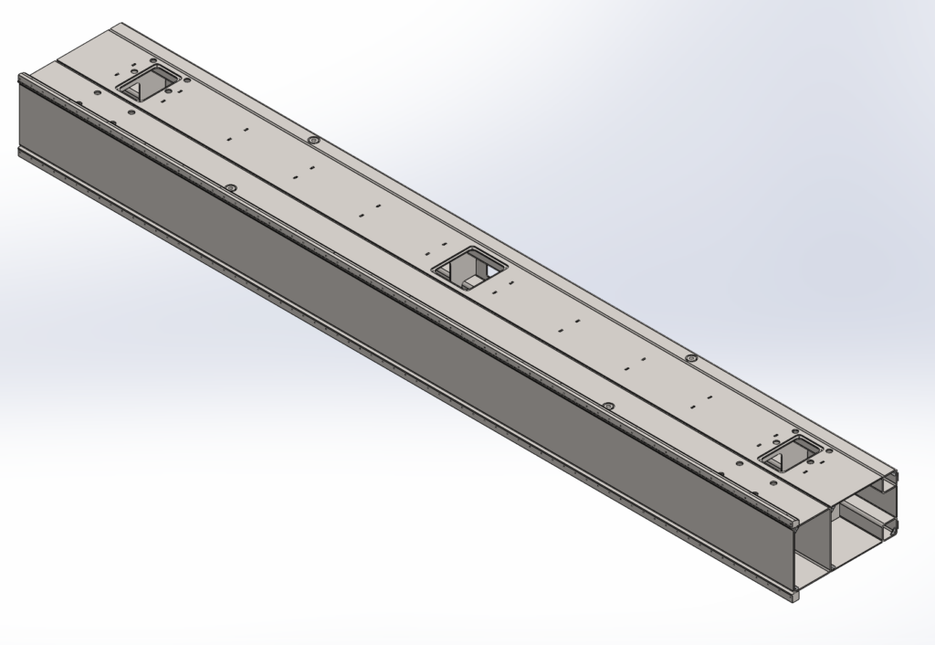
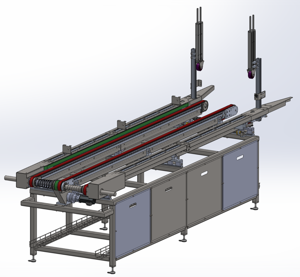
The conveyor transports cartons, into which two robots insert cardboard absorbers. The cartons come in various lengths and widths.
Challenge
For the robot to glue the absorber, the system must know the exact position of the cartons throughout the entire transport. For the adhesive to adhere, the absorber must be pressed against the carton wall, which can cause it to shift on the conveyor.
Solution
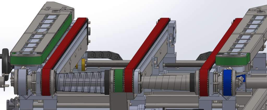
Two side straps lightly compress the cardboard, providing adequate traction.
Another challenge
Synchronization of the bottom and side straps.
In the required configuration, it’s impossible to use off-the-shelf bevel gears. They simply don’t exist. A more complex, multi-element drivetrain would be required.
The solution turned out to be a twisted toothed belt transmission, which connects two wheels with axles that are turned 90 degrees to each other, but not lying in one plane.
A furniture company was having trouble with foam cutouts. Many of the pieces were similar, so they often got mixed up. This made it difficult to sort and assign them to specific products. Product quality was variable when similar yet different pieces were used in the production process. Significant time was lost on rework.
The solution was to mark the sponge before cutting it.
My role:
Design of the entire supporting structure and mechanisms
Reverse engineering – complete 3D model of the existing press
Design of new mechanical components and pneumatic cover
Cooperation in creating the hydraulic diagram and selecting components
Preparation of manufacturing drawings with GD&T
Creation of BOM lists for new parts and hydraulic components
Application of DFA/DFM principles
Supervision of fabrication, assembly and commissioning
Project description
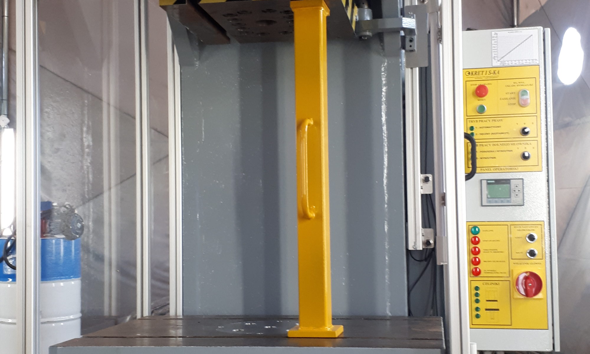
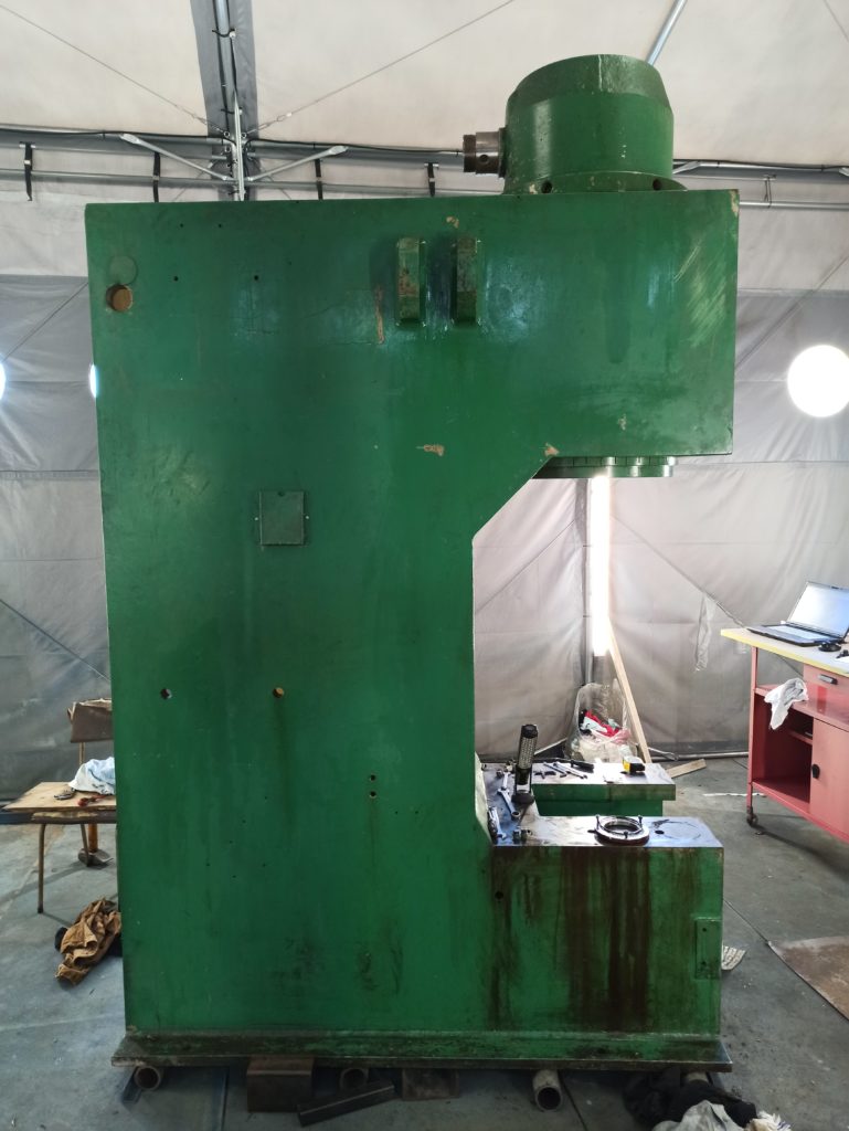
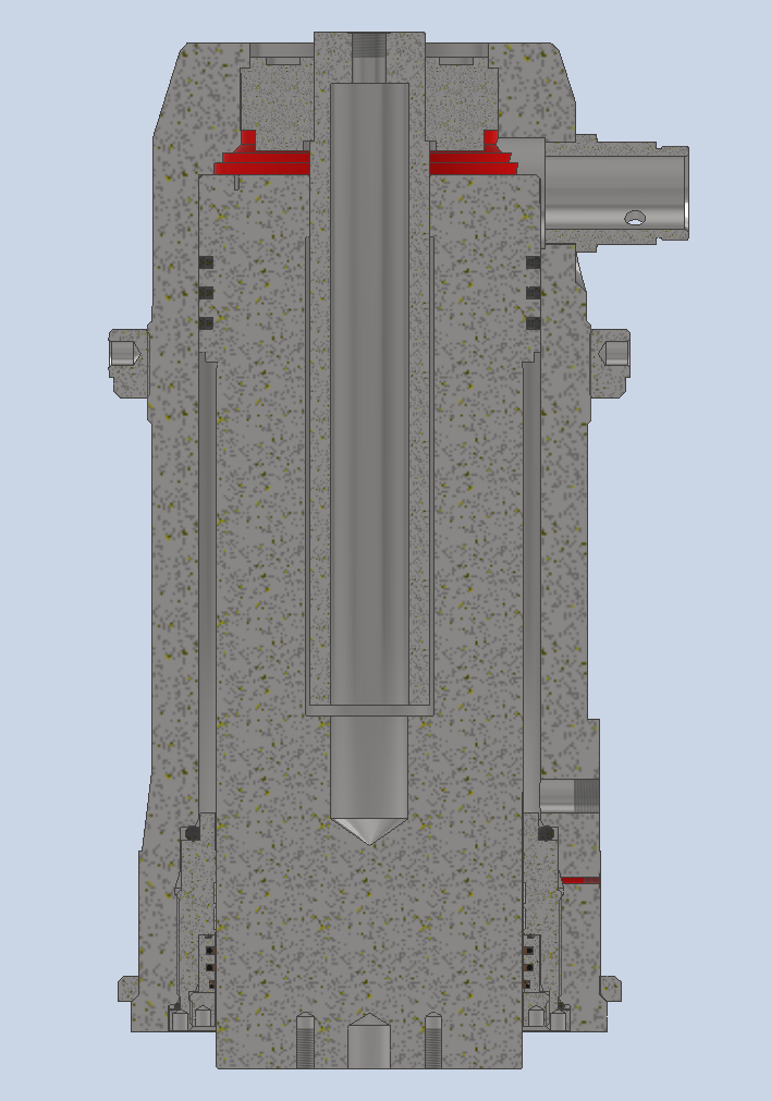
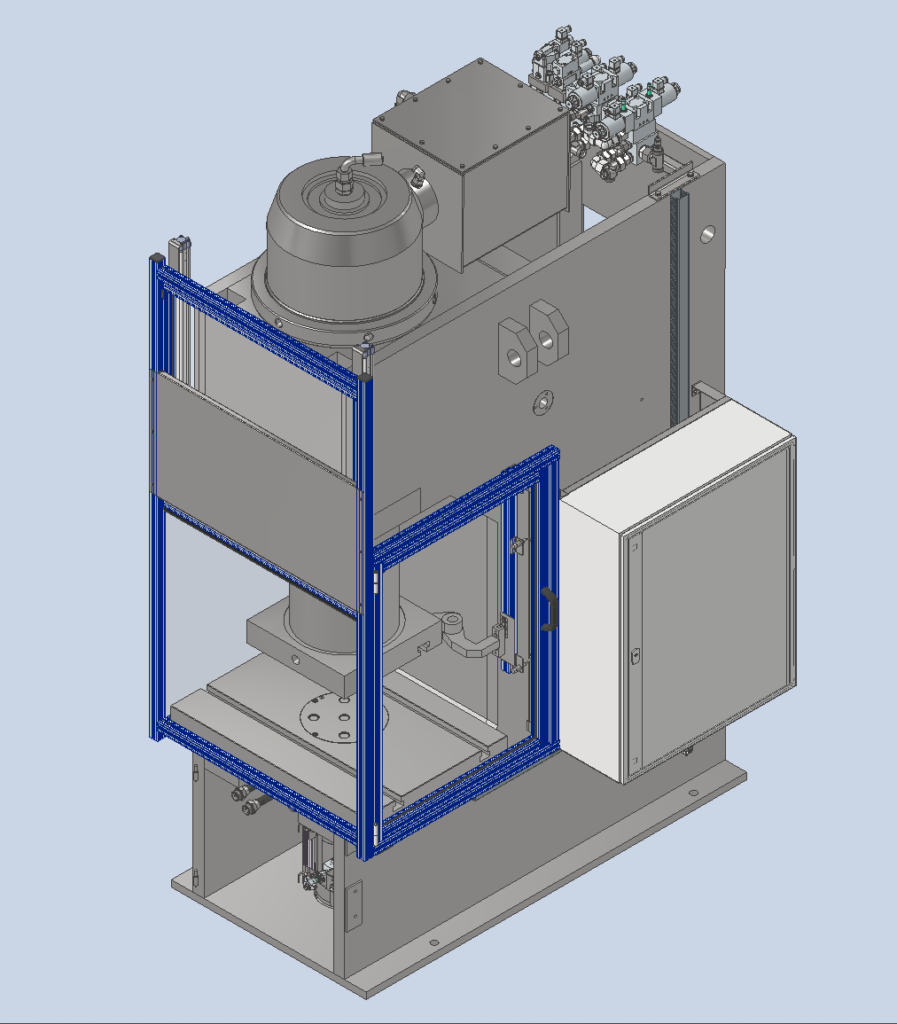
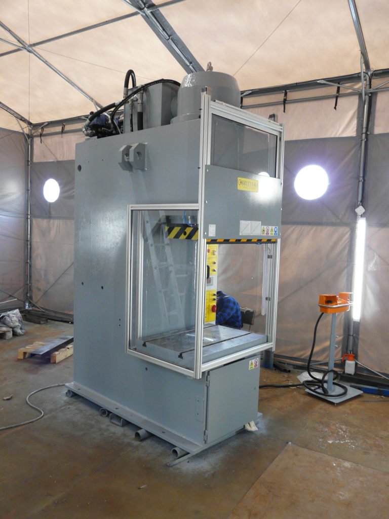
The client had an old, worn-out press. It no longer met health and safety standards, and had leaks and other defects. However, the body and main cylinder were in good condition. So we undertook a thorough modernization.
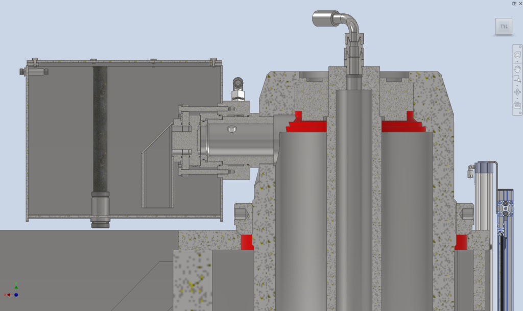
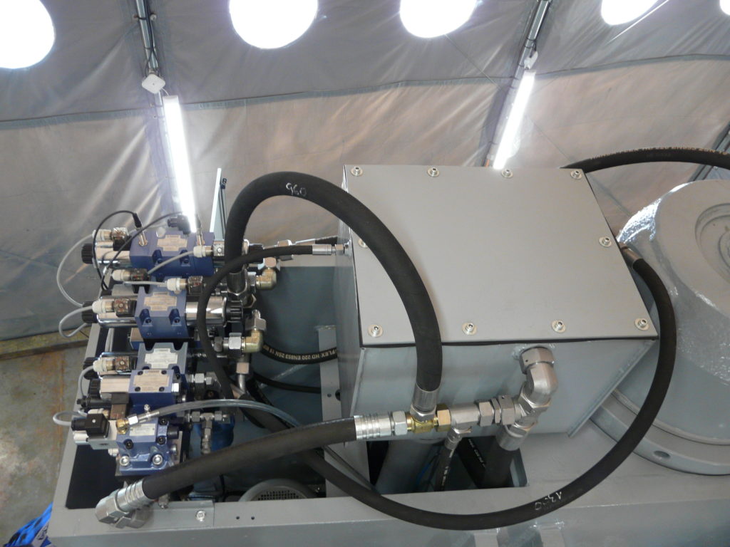
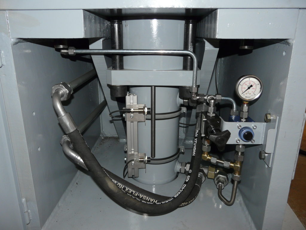
We designed a new hydraulic system, re-creating the rapid movement system with a flood tank.
We have regenerated the main cylinder piston rod and changed the type of seals used in the entire cylinder.
We designed a workspace cover with a pneumatically raised shutter.
Development and construction of a device for riveting bodywork elements using RIVSET rivets.
My role:
Designer – Mechanical Part
Layout Development
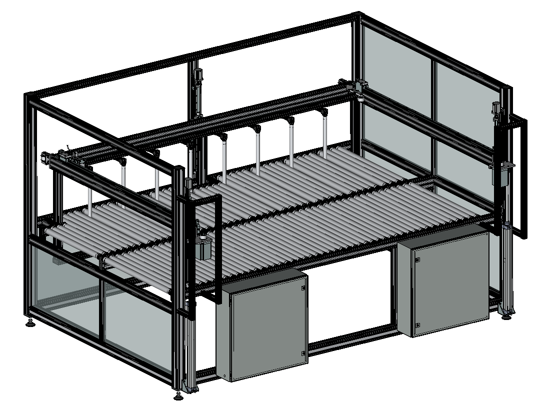
Preparation of a preliminary design (3D model) and drawings for client verification
Technical Design
FEM strength analysis of selected components to achieve appropriate stiffness to ensure precision and repeatability
Construction documentation
Project description
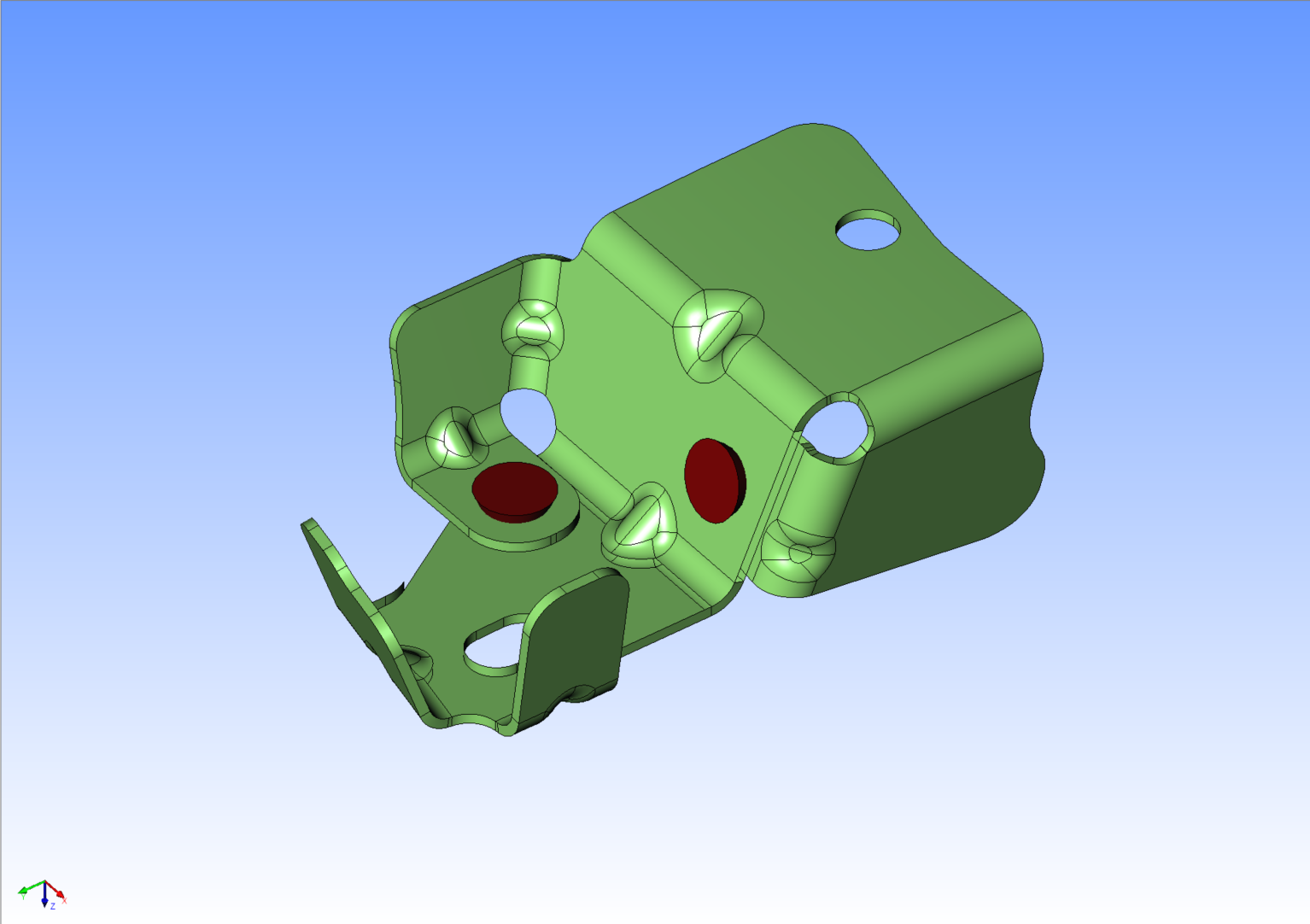
The cut, embossed element should then be riveted with two rivets in the next step. The element is available in left- and right-hand versions. The riveting points are located on two surfaces. Both versions should be riveted on a single machine.
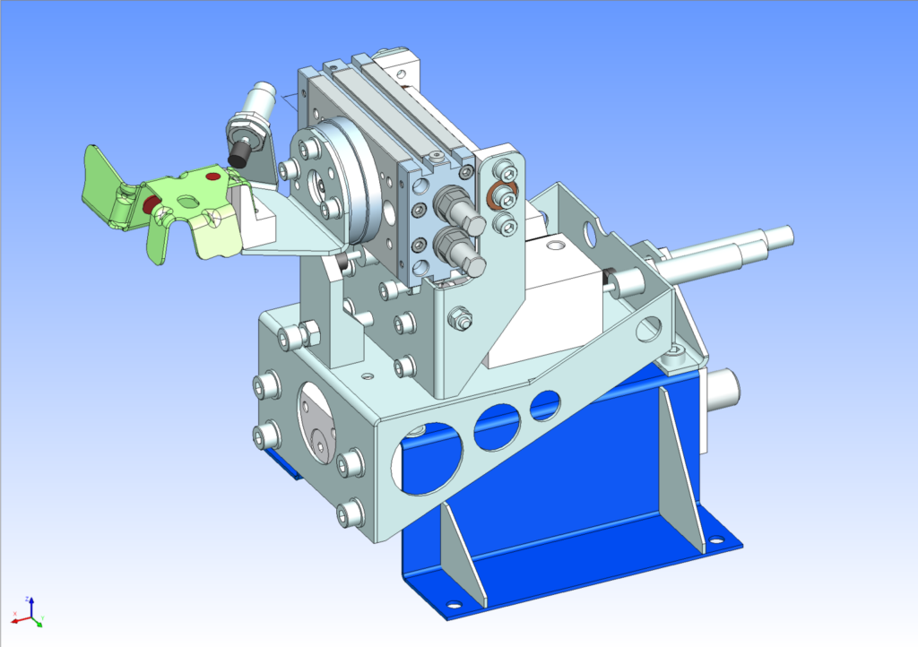
By selecting the appropriate sequence of movements, I found a position and method for gripping the part that allowed for both joints to be made with a single clamping operation. Clamping the part in the machine is greatly simplified and accelerated by an additional swing arm, at the end of which is a socket that maps the shape of the part.
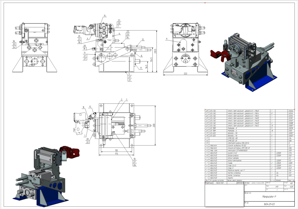
The machine is designed to perform a single operation on a single type of component. Therefore, movements are performed by pneumatic actuators with built-in guides and adjustable end positions. This ensures speed, reliability, and repeatability at an affordable price.
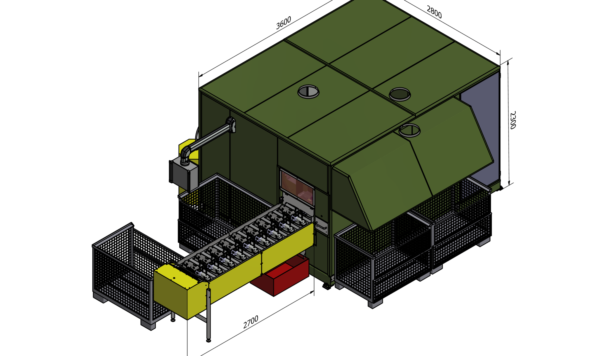
We worked as a partner responsible for the design and construction of the mechanical part and the cell housing.
My role:
Layout development and workspace analysis for three robots
Design of dedicated conveyor with Poka-Yoke nests
Full mechanical design of the cell structure
Preparation of manufacturing drawings including GD&T and welding documentation
BOM creation
FEM analysis of critical components
Application of DFA/DFM principles (cost reduction of nests, ease of assembly)
Coordination of the work of the design and automation teams
Supervision of production, assembly, FAT
Project description
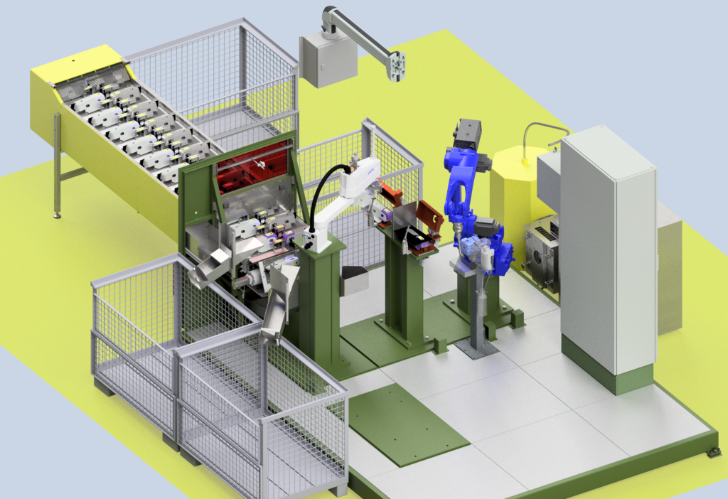
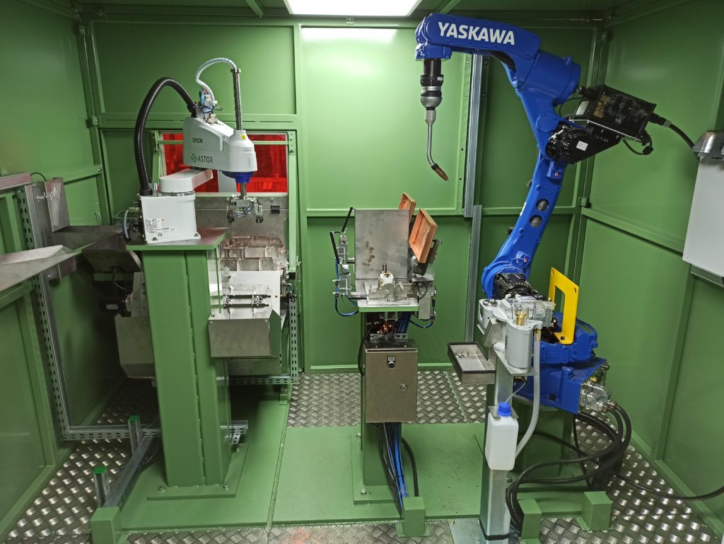
The Welding Cell is a comprehensive solution that ensures the assembly of parts and their connection in the welding process.
The operator takes out the components from baskets located next to the Cell and places them on a conveyor. Shaped nests ensure proper part placement (they cannot be placed in the wrong nest or in a different orientation). Both left-hand and right-hand parts are simultaneously placed on one conveyor section. Additionally, the parts on the conveyor pass through a shaped gate, which serves as a second level of inspection and a safety feature that stops the machine if other items are left on the conveyor. The final checkpoint before assembly, located inside the Cell, is the presence and orientation check, ensured by a vision system.
Two robots operate inside the housing. The first, a SCARA, picks up both parts from the conveyor and assembles them directly on the welding cells. The welding is performed by the second robot, this time a 6-axis robot. After welding, the SCARA removes the finished parts and places them in the appropriate discharge chutes.
In the Cell, “right” and “left” workpieces are welded alternately. While welding is taking place on one workpiece, the other is emptied and the next workpiece is assembled on it.
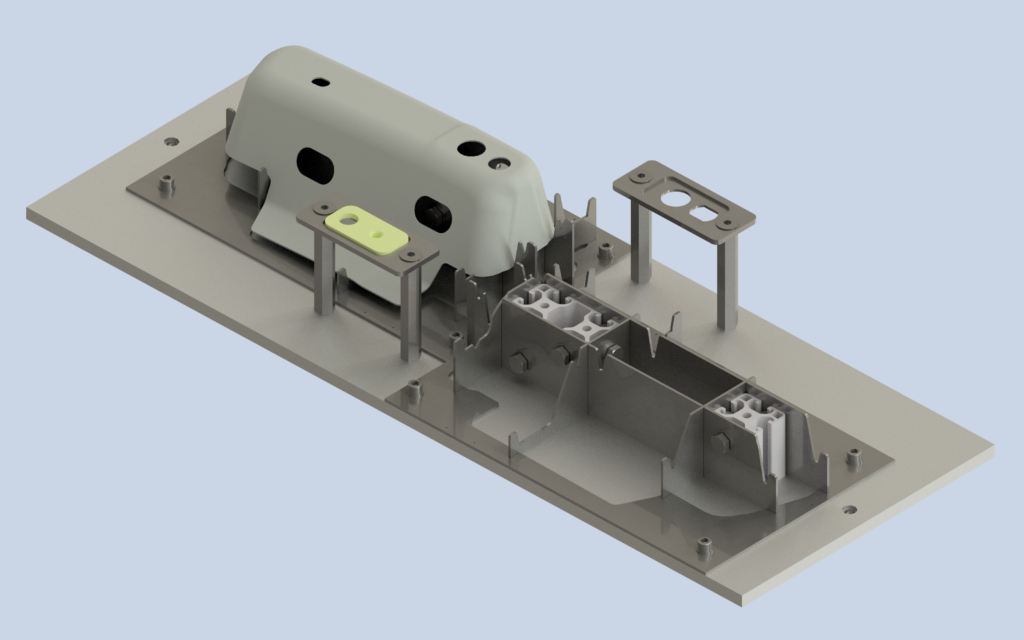
The process involves welding a thick, small component with two holes to a sheet metal stamping. To ensure process continuity, we designed a buffer conveyor. It has 24 pairs of shaped nests to ensure flawless part alignment. Due to the large number of nests, manufacturing them as individual blocks would be very expensive, so I developed a much cheaper version based on five cross-sections.
Currently, the cell is staffed by one welding robot. If the need arises to increase production speed, there is space for a second welding station with a second robot.
Types of effects obtained as a result of work implementation
Work safety:
Clean air – the assembly and welding process takes place in a closed space, the extraction system ensures a slight negative pressure inside.
Eye protection – the cell housing provides full protection against radiation generated during welding.
Design:
The conveyor’s shaped nests ensure proper positioning of the parts on the conveyor, ensuring their smooth pickup by the robot. The conveyor consists of 26 plates, with two nests on each plate. Creating this many nests using subtractive or additive machining would be prohibitively expensive. Therefore, the component shapes were modeled using selected cross-sections. Five cross-sections were required for the parts in this process, plus a contour sheet to facilitate nest identification by the operator. Their total cost for the entire conveyor is comparable to the cost of producing one plate (two pockets) using subtractive methods.
Ergonomics:
The operator places the components on a segmented feed conveyor, which is designed to prevent incorrect positioning of the parts.
The conveyor serves as a buffer of parts for the process, which provides the operator with sufficient time for other process-related activities (replacing the container with the finished product, providing input components at the loading station, etc.), without compromising the efficiency and repeatability of the process.
Economy:
The cell supports 2 types of elements without the need for retooling.
The machine is distinguished by its ease of use – the process does not require the operator to assemble the input parts that are components of the finished product (we exclude incorrect assembly and reduce time).
The finished product is produced in less than 22 seconds (the customer’s requirement was 22 seconds – 160 pieces/hour). After optimizing the welding process (MAG pulse welding), the machine achieved a maximum output of 200 pieces/hour.
In fact, the surplus time we gained after process optimization was used for maintenance breaks (cleaning of welding stations every 4 hours of work)
Quality:
The completeness of the parts placed on by the operator is checked by the vision system.
A welding robot integrated with an advanced power source ensures high quality and repeatability of the welding process.
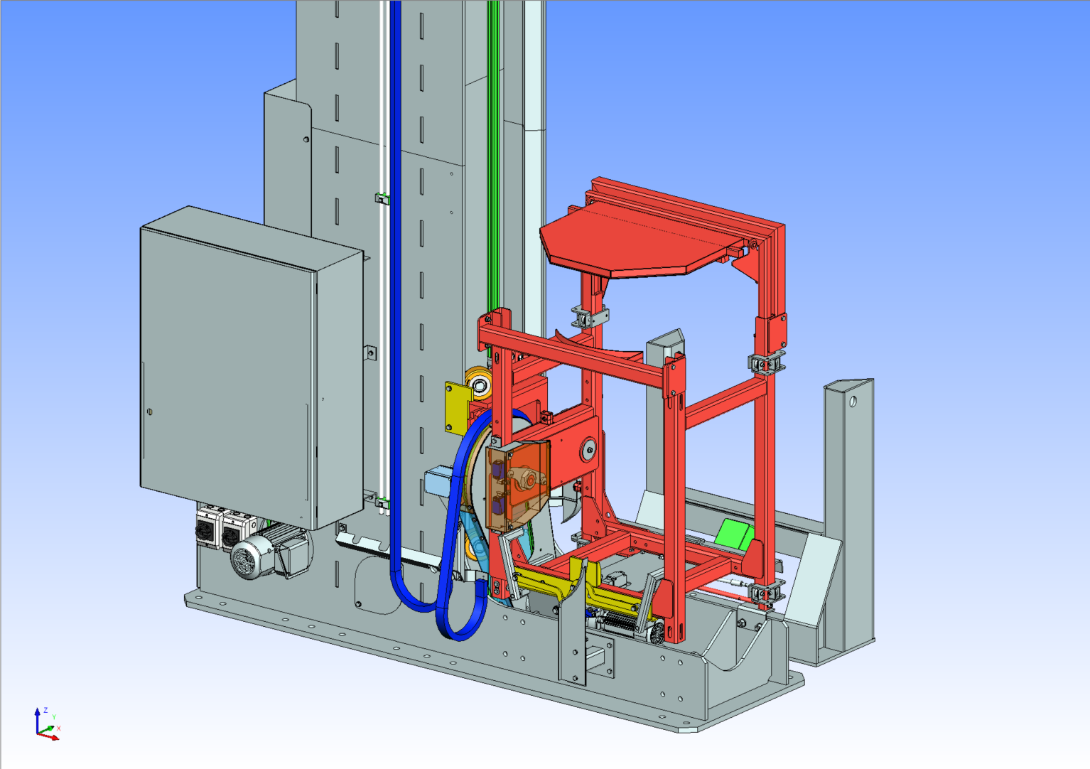
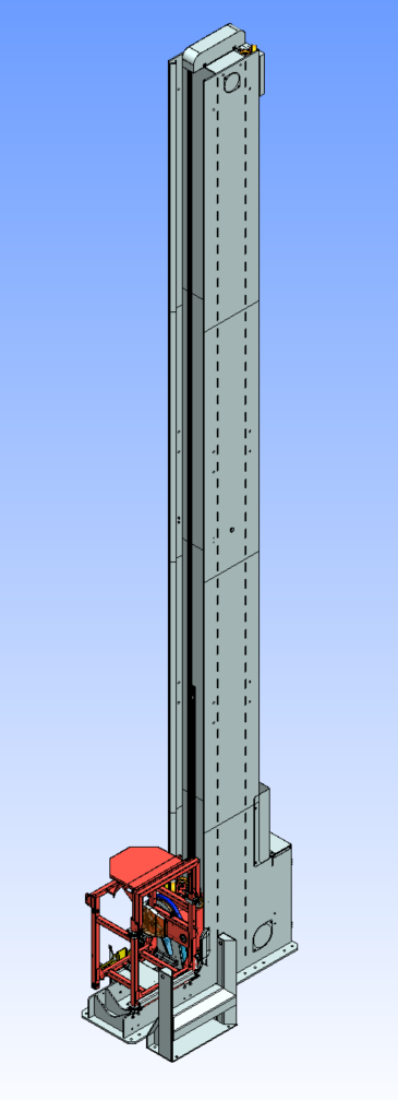
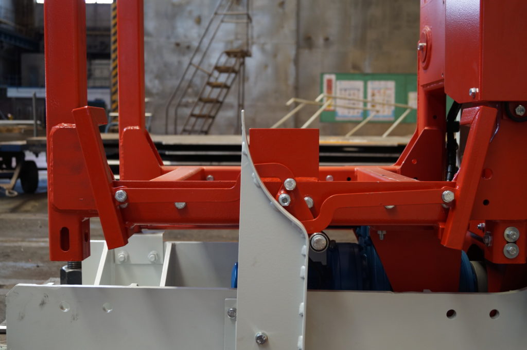
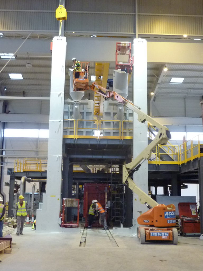
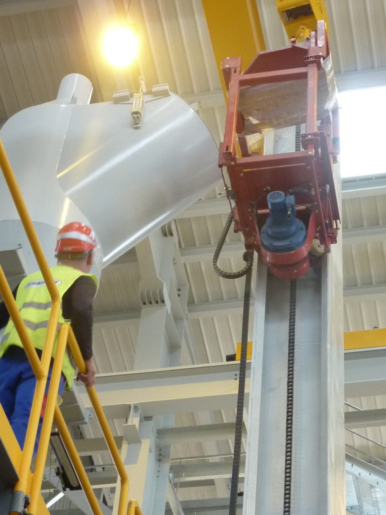
The project involved the development and construction of dedicated lifts for feeding the furnace for smelting titanium waste.
My role:
Project Manager, Designer.
Project conducted for a Polish-American company, with most of the dialogue conducted in English. Preparation of the lift concept based on the assumptions contained in the request for proposal. Presentation of the solution concept, receipt of comments and questions. Implementation of changes. Preparation of a preliminary design (3D model), drawings, and animations for client verification of the solution (incorporating the lifts into the overall design). Co-creation of a price and time offer. Analysis of the causes and effects of defects, as well as their impact and criticality on the production process (FMEA). Technical design. FEM strength analysis. Design documentation. Supervision of part production and assembly. Commissioning and conducting factory tests. Participation in factory acceptance tests (FAT).